CP53/CP54/CP55 Capacitors List
Below is the list of available Capacitance and Voltage for our CP53/CP54/CP55 MIL Spec Capacitors.
For immediate quoting, contact us now!
The tables below are divided in several sections. Each section are for an specific circuit diagram. Refer to the figure below:
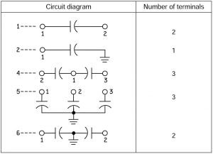
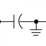
NOTE: For circuit diagram 4, the common terminal is marked “C” on the case.
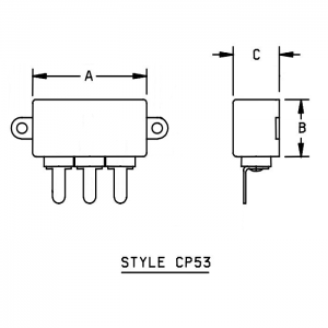
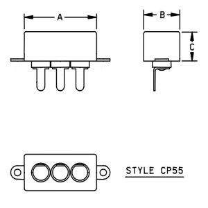
In the tables, an “n” can be replaced with a “3”, “4”, or “5” to indicate one of the case styles below, which are distinguished by the side of the case on which the terminals are located. The number of terminals is determined by the circuit diagram, a schematic of which is shown above which describes capacitors specified for that circuit diagram.

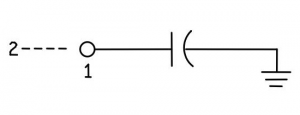
| Circuit Diagram 1 Two Terminals | One Winding |
.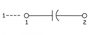 . . |
||||
| MODEL | VOLT | CAP (uF) | A (in) | B (in) | C (in) |
| CP5nB1EB105K1 | 100 | 1 | 1.81 | 1.00 | 0.875 |
| CP5nB1FB105K1 | 100 | 1 | 1.81 | 1.00 | 0.750 |
| CP5nB1EB205K1 | 100 | 2 | 2.00 | 1.75 | 0.875 |
| CP5nB1EB405K1 | 100 | 4 | 2.00 | 2.00 | 1.125 |
| CP5nB1FB405K1 | 100 | 4 | 2.00 | 2.00 | 1.000 |
| CP5nB1FC504K1 | 200 | 0.5 | 1.81 | 1.00 | 0.750 |
| CP5nB1EC105K1 | 200 | 1 | 2.00 | 1.75 | 0.875 |
| CP5nB1EC205K1 | 200 | 2 | 2.00 | 2.00 | 1.000 |
| CP5nB1KE503K1 | 400 | 0.05 | 1.81 | 1.00 | 0.750 |
| CP5nB1KE104K1 | 400 | 0.1 | 1.81 | 1.00 | 0.750 |
| CP5nB1KE254K1 | 400 | 0.25 | 1.81 | 1.00 | 0.750 |
| CP5nB1KE504K1 | 400 | 0.5 | 1.81 | 1.00 | 0.875 |
| CP5nB1KE105K1 | 400 | 1 | 2.00 | 1.75 | 0.875 |
| CP5nB1EF254K1 | 600 | 0.25 | 1.81 | 1.00 | 0.750 |
| CP5nB1EF504K1 | 600 | 0.5 | 1.81 | 1.00 | 1.000 |
| CP5nB1FF504K1 | 600 | 0.5 | 1.81 | 1.00 | 0.875 |
| CP5nB1EF105K1 | 600 | 1 | 2.00 | 1.75 | 1.000 |
| CP5nB1FF105K1 | 600 | 1 | 2.00 | 1.75 | 0.875 |
| CP53B1EF205K1 | 600 | 2 | 2.00 | 2.00 | 1.125 |
| CP54B1FF205K1 | 600 | 2 | 2.00 | 2.00 | 1.250 |
| CP55B1EF205K1 | 600 | 2 | 2.00 | 2.00 | 1.250 |
| CP5nB1EG503K1 | 1000 | 0.05 | 1.81 | 1.00 | 0.750 |
| CP5nB1EG104K1 | 1000 | 0.1 | 1.81 | 1.00 | 0.750 |
| CP5nB1EG254K1 | 1000 | 0.25 | 1.81 | 1.00 | 0.875 |
| CP5nB1FG254K1 | 1000 | 0.25 | 1.81 | 1.00 | 0.750 |
| CP5nB1EG504K1 | 1000 | 0.5 | 2.00 | 1.75 | 0.875 |
| CP53B1EG105K1 | 1000 | 1 | 2.00 | 2.00 | 1.125 |
| CP54B1EG105K1 | 1000 | 1 | 2.00 | 2.00 | 1.250 |
| CP55B1EG105K1 | 1000 | 1 | 2.00 | 2.00 | 1.250 |
| Dimensions subject to change as design improvements are made. Updated Dimensions will be provided with each Request for Quote. |
|||||
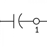
| Circuit Diagram 2 One Terminal | One Winding |
 |
||||
| MODEL | VOLT | CAP (uF) | A (in) | B (in) | C (in) |
| CP5nB2EB205K1 | 100 | 1 | 1.81 | 1.00 | 0.875 |
| CP5nB2FB205K1 | 100 | 1 | 1.81 | 1.00 | 0.750 |
| CP5nB2EB205K1 | 100 | 2 | 2.00 | 1.75 | 0.875 |
| CP5nB2EB405K1 | 100 | 4 | 2.00 | 2.00 | 1.125 |
| CP5nB2FB405K1 | 100 | 4 | 2.00 | 2.00 | 1.000 |
| CP5nB2FC504K1 | 200 | 0.5 | 1.81 | 1.00 | 0.750 |
| CP5nB2EC105K1 | 200 | 1 | 2.00 | 1.75 | 0.875 |
| CP5nB2EC205K1 | 200 | 2 | 2.00 | 2.00 | 1.000 |
| CP5nB2KE503K1 | 400 | 0.05 | 1.81 | 1.00 | 0.750 |
| CP5nB2KE104K1 | 400 | 0.1 | 1.81 | 1.00 | 0.750 |
| CP5nB2KE254K1 | 400 | 0.25 | 1.81 | 1.00 | 0.750 |
| CP5nB2KE504K1 | 400 | 0.5 | 1.81 | 1.00 | 0.875 |
| CP5nB2KE105K1 | 400 | 1 | 2.00 | 1.75 | 0.875 |
| CP5nB2EF254K1 | 600 | 0.25 | 1.81 | 1.00 | 0.750 |
| CP5nB2EF504K1 | 600 | 0.5 | 1.81 | 1.00 | 1.000 |
| CP5nB2FF504K1 | 600 | 0.5 | 1.81 | 1.00 | 0.875 |
| CP5nB2EF105K1 | 600 | 1 | 2.00 | 1.75 | 1.000 |
| CP5nB2FF105K1 | 600 | 1 | 2.00 | 1.75 | 0.875 |
| CP53B2EF205K1 | 600 | 2 | 2.00 | 2.00 | 1.125 |
| CP54B2FF205K1 | 600 | 2 | 2.00 | 2.00 | 1.250 |
| CP55B2EF205K1 | 600 | 2 | 2.00 | 2.00 | 1.250 |
| CP5nB2EG503K1 | 1000 | 0.05 | 1.81 | 1.00 | 0.750 |
| CP5nB2EG104K1 | 1000 | 0.1 | 1.81 | 1.00 | 0.750 |
| CP5nB2EG254K1 | 1000 | 0.25 | 1.81 | 1.00 | 0.875 |
| CP5nB2FG254K1 | 1000 | 0.25 | 1.81 | 1.00 | 0.750 |
| CP5nB2EG504K1 | 1000 | 0.5 | 2.00 | 1.75 | 0.875 |
| CP53B2EG105K1 | 1000 | 1 | 2.00 | 2.00 | 1.125 |
| CP54B2EG105K1 | 1000 | 1 | 2.00 | 2.00 | 1.250 |
| CP55B2EG105K1 | 1000 | 1 | 2.00 | 2.00 | 1.250 |
| Dimensions subject to change as design improvements are made. Updated Dimensions will be provided with each Request for Quote. |
|||||
| Circuit Diagram 4 Three Terminals | Two Windings |
 |
||||
| MODEL | VOLT | CAP (uF) | A (in) | B (in) | C (in) |
| CP5nB4EF503V1 | 600 | 2 x 0.05 | 1.81 | 1.00 | 0.750 |
| CP5nB4EF104V1 | 600 | 2 x 0.1 | 1.81 | 1.00 | 0.750 |
| CP5nB4EF254V1 | 600 | 2 x 0.25 | 1.81 | 1.00 | 1.000 |
| CP5nB4FF254V1 | 600 | 2 x 0.25 | 1.81 | 1.00 | 0.875 |
| CP5nB4EF504V1 | 600 | 2 x 0.5 | 2.00 | 1.75 | 1.000 |
| CP5nB4FF504V1 | 600 | 2 x 0.5 | 2.00 | 1.75 | 0.875 |
| CP53B4EF105V1 | 600 | 2 x 1 | 2.00 | 2.00 | 1.125 |
| CP54B4EF105V1 | 600 | 2 x 1 | 2.00 | 2.00 | 1.250 |
| CP55B4EF105V1 | 600 | 2 x 1 | 2.00 | 2.00 | 1.250 |
| CP5nB4EG503V1 | 1000 | 2 x 0.05 | 1.81 | 1.00 | 0.750 |
| CP5nB4EG104V1 | 1000 | 2 x 0.1 | 1.81 | 1.00 | 0.875 |
| CP5nB4FG104V1 | 1000 | 2 x 0.1 | 1.81 | 1.00 | 0.750 |
| CP5nB4EG254V1 | 1000 | 2 x 0.25 | 2.00 | 1.75 | 0.875 |
| CP53B4EG504V1 | 1000 | 2 x 0.5 | 2.00 | 2.00 | 1.125 |
| CP54B4EG504V1 | 1000 | 2 x 0.5 | 2.00 | 2.00 | 1.250 |
| CP55B4EG504V1 | 1000 | 2 x 0.5 | 2.00 | 2.00 | 1.250 |
| Dimensions subject to change as design improvements are made. Updated Dimensions will be provided with each Request for Quote. |
|||||
| Circuit Diagram 5 Three Terminals | Three Windings |
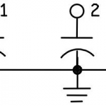 |
||||
| MODEL | VOLT | CAP (uF) | A (in) | B (in) | C (in) |
| CP5nB5EE504V1 | 400 | 3 x 0.5 | 2.00 | 2.00 | 1.125 |
| CP5nB5FE504V1 | 400 | 3 x 0.5 | 2.00 | 2.00 | 1.000 |
| CP5nB5EF104V1 | 600 | 3 x 0.1 | 1.81 | 1.00 | 0.875 |
| CP5nB5FF104V1 | 600 | 3 x 0.1 | 1.81 | 1.00 | 0.750 |
| CP5nB5EF254V1 | 600 | 3 x 0.25 | 2.00 | 1.75 | 0.875 |
| CP53B5EF504V1 | 600 | 3 x 0.5 | 2.00 | 2.00 | 1.125 |
| CP54B5EF504V1 | 600 | 3 x 0.5 | 2.00 | 2.00 | 1.250 |
| CP55B5EF504V1 | 600 | 3 x 0.5 | 2.00 | 2.00 | 1.250 |
| CP5nB5EG503V1 | 1000 | 3 x 0.05 | 1.81 | 1.00 | 0.750 |
| CP5nB5EG104V1 | 1000 | 3 x 0.1 | 2.00 | 1.75 | 0.875 |
| CP53B5EG254V1 | 1000 | 3 x 0.25 | 2.00 | 2.00 | 1.125 |
| CP54B5EG254V1 | 1000 | 3 x 0.25 | 2.00 | 2.00 | 1.250 |
| CP55B5EG254V1 | 1000 | 3 x 0.25 | 2.00 | 2.00 | 1.250 |
| Dimensions subject to change as design improvements are made. Updated Dimensions will be provided with each Request for Quote. |
|||||
| Circuit Diagram 6 Two Terminals | Two Windings |
 |
||||
| MODEL | VOLT | CAP (uF) | A (in) | B (in) | C (in) |
| CP5nB6EF503V1 | 600 | 2 x 0.05 | 1.81 | 1.00 | 0.750 |
| CP5nB6EF104V1 | 600 | 2 x 0.1 | 1.81 | 1.00 | 0.750 |
| CP5nB6EF254V1 | 600 | 2 x 0.25 | 1.81 | 1.00 | 1.000 |
| CP5nB6FF254V1 | 600 | 2 x 0.25 | 1.81 | 1.00 | 0.875 |
| CP5nB6EF504V1 | 600 | 2 x 0.5 | 2.00 | 1.75 | 1.000 |
| CP5nB6FF504V1 | 600 | 2 x 0.5 | 2.00 | 1.75 | 0.875 |
| CP53B6EF105V1 | 600 | 2 x 1 | 2.00 | 2.00 | 1.125 |
| CP54B6EF105V1 | 600 | 2 x 1 | 2.00 | 2.00 | 1.250 |
| CP55B6EF105V1 | 600 | 2 x 1 | 2.00 | 2.00 | 1.250 |
| CP5nB6EG503V1 | 1000 | 2 x 0.05 | 1.81 | 1.00 | 0.750 |
| CP5nB6EG104V1 | 1000 | 2 x 0.1 | 1.81 | 1.00 | 0.875 |
| CP5nB6FG104V1 | 1000 | 2 x 0.1 | 1.81 | 1.00 | 0.750 |
| CP5nB6EG254V1 | 1000 | 2 x 0.25 | 2.00 | 1.75 | 0.875 |
| CP53B6EG504V1 | 1000 | 2 x 0.5 | 2.00 | 2.00 | 1.125 |
| CP54B6EG504V1 | 1000 | 2 x 0.5 | 2.00 | 2.00 | 1.250 |
| CP55B6EG504V1 | 1000 | 2 x 0.5 | 2.00 | 2.00 | 1.250 |
| Dimensions subject to change as design improvements are made. Updated Dimensions will be provided with each Request for Quote. |
|||||